
 Neewer NL660-2.4 Video Keylight Panel with remote
The need for a DIY remote
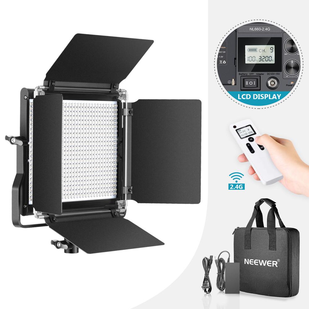
Neewer makes decent light panels for photography, video, and streaming. Their flagship high-CRI temperature adjustable NL660-2.4 panels1 are around half the price of an Elgato Key Light, and come with a wireless remote to control them. I recently picked up a pair of them, and I’m very happy with their light quality and brightness.
The remote is also nice, but has one major pitfall: it doesn’t have a button to turn on the lights with their previous brightness setting. As I use my two panels at different angles and distances to my face, they each have their own ideal brightness.
Setting them up individually each time requires about a dozen button presses. I would like to have them both just turn off/on to their previous setting, and so I wondered if it’s possible to make our own remote for it. Let’s dive in!
Some reconnaissance
Most wireless consumer devices are required to pass radio interference testing. Oftentimes, there will be an approval ID from FCC or other organisations stamped somewhere on the device, and searching online for these IDs often brings up helpful information like pictures of PCBs and reports on wireless methods used.
This remote was no exception, and a quick online search yielded a full test report from Japanese authorities, including PCB pictures. The pictures were not high quality enough to identify chip names, but the report did mention that the remote communicates at 2410MHz using GFSK, at 250kb/s.
 Neewer NL660-2.4 RT-100 radio interference test report
Bluetooth and ZigBee are two widely used wireless technologies that use GFSK at 2.4GHz, but scanning for traffic on either ended up without results. So let’s move on to disassemble the remote in the hopes of identifying what chips it uses for communication.
Disassembly time
Opening up the Neewer remote is luckily very easy: its two parts are held together with snap fit joints and no glue at all. Yay for repairability!
Once inside, we see that the brains of the remote is an 8-bit STM8L152C6T6 microcontroller, and it’s communicating via an SI24R1.
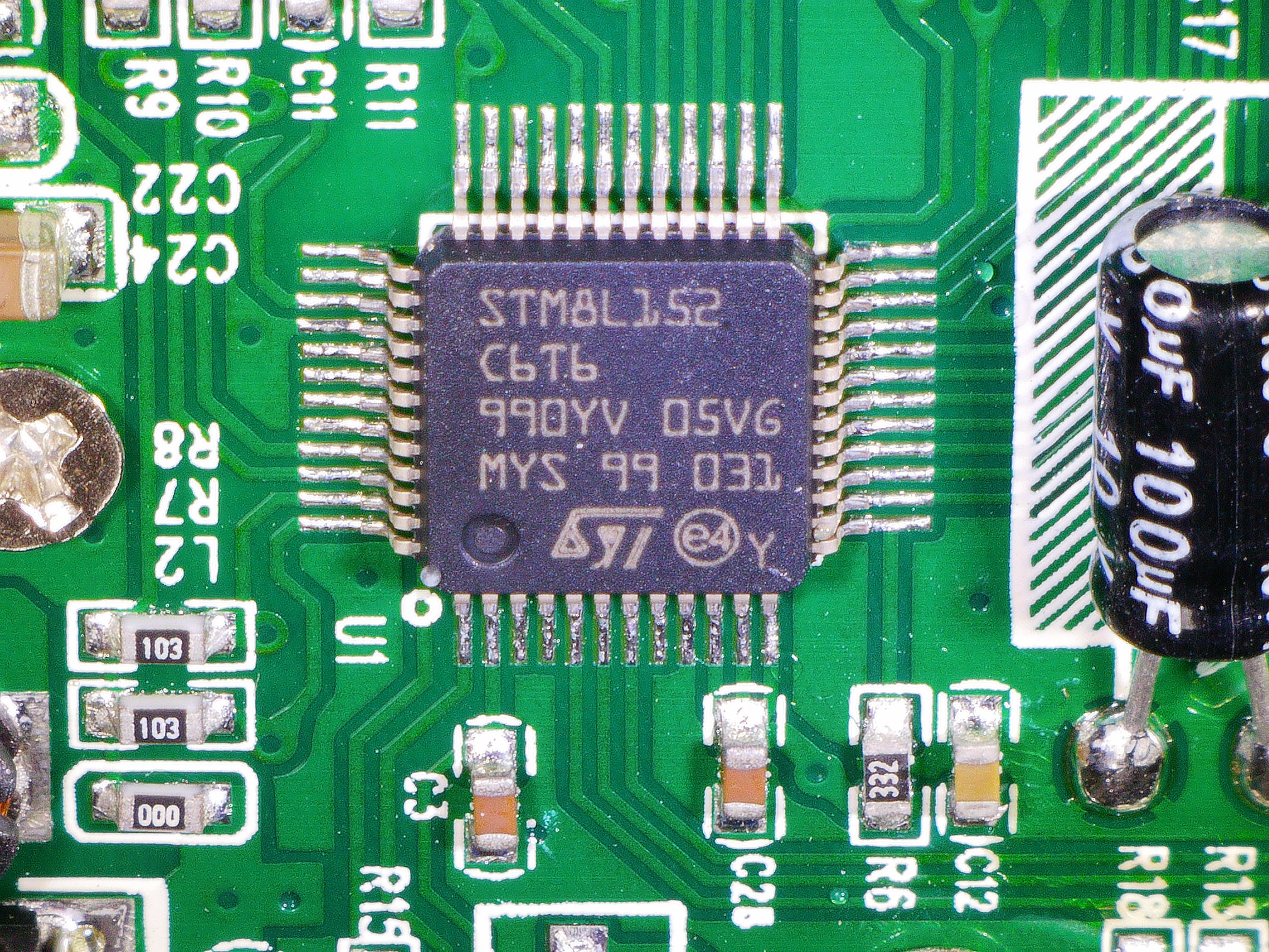
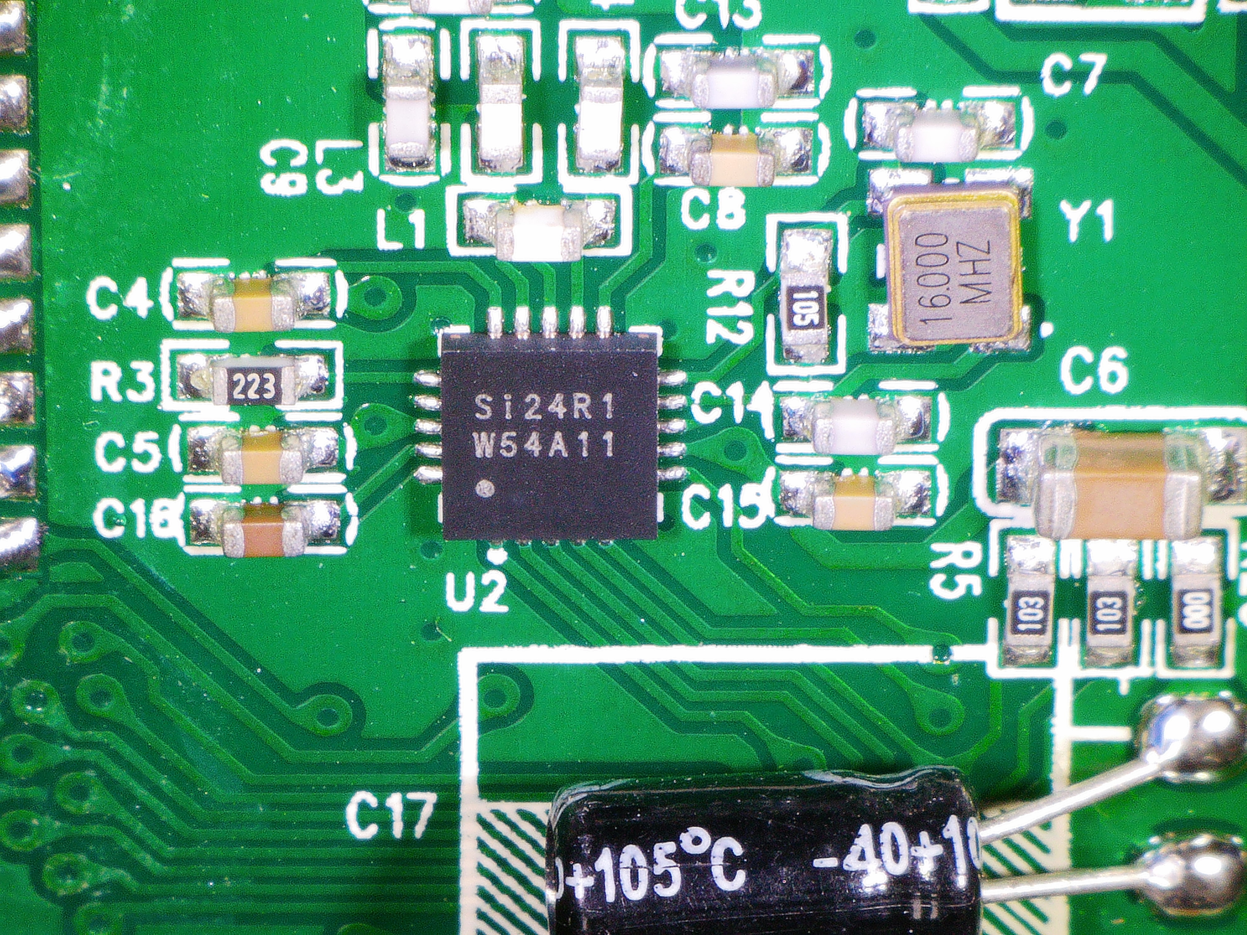
Microscope shots of the microcontroller (left) and the radio IC (right)
A quick online search shows that the SI24R1 is a clone of the widely used Nordic NRF24L01. I had one of those laying around, but using them to snoop traffic is not that easy: the NRF24 requires you to provide a physical channel (frequency), a packet destination address, and a few other details like packet length. It has no promiscuous mode where it just dumps all packets it sees.
Travis Goodspeed wrote a wonderful blog post about how you can trick the NRF24 into spilling the beans anyway, but it still requires you to try 65536 different addresses per channel (and there are 100+ of those). Let’s try instead to dump the STM8’s firmware and read the NRF24 info we need from there.
Dumping the STM8
STM8-family ICs can be debugged using ST’s SWIM protocol. Thankfully, Neewer was kind enough to expose a 4-pin SWIM debug header right next to the STM8. From the STM8L152C6T6 datasheet we can trace the SWIM pins with a multimeter to the debug port, and find the following pinout:
 The PCB has an exposed SWIM debug port for its STM8
At this point you can use the ST Visual Programmer tool (note: windows-only) together with an STLink-v2 compatible debugger to attach to the STM8. Unfortunately, we are greeted by an error message when we try to dump its flash storage:
 Too bad: readout protection prevents dumping flash storage
Ok, so Neewer burnt the e-fuse that permits a debugger from reading flash contents. Whilst there is a way to break this readout protection using voltage glitching, it’s not the easiest route for now.
Snooping the SPI bus
Since all we want is to know the initialisation details of the SI24R1 and the packet protocol, dumping or changing the STM8 firmware is not really important. Instead, we can also simply listen in on the SPI bus that the STM8 uses to initialise the SI24R1 and send packet data. This time, we dive into SI24’s datasheet and find its SPI pins. They are not broken out to testpoints on the PCB, and because the SI24 has small pads that are hard to solder wires to, it’s easier to trace the pins to where they connect on the STM8. The big pins there allow us to solder to our heart’s content. Here’s the pinout of the SPI bus:
 SPI pinout from the STM8 to the SI24
Time to solder some bodge wires to the pins (as they are not big enough to directly attach probes to), and hook up a logic analyser. For these kinds of bus signals with low frequencies (i.e. not hundreds of MHz+) and low number of pins, any logic analyser will do.
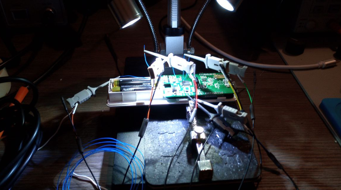 Wires soldered to the SPI pins, connected to a logic analyser to dump SPI traffic
Firing up the logic analyser, powering on the remote, and pressing a button immediately looks promising:
 SPI bus data, sent when pressing a button. The first 4 bytes shown here configure the TX address
Neewer’s NRF24 wireless configuration
On every button press, the STM8 resends the entire configuration to the SI24, including send/receive address, channel frequency, data length, etc. Here’s an overview of how the SI24 gets set up:
| Option | Value |
|---|---|
| Addres width | 3 bytes |
| TX address | 0xD35C6E (big-endian / MSB sent first) |
| RX address | Same as TX address |
| TX Channel | 10 (2410 MHz) |
| TX Power | Max |
| Bitrate | 250Kb/s |
| Payload length | 32 bytes |
| Checksum | CRC16 |
| Auto ack | No |
| Dynamic payload length | No |
Neewer’s remote control protocol
Next, onto the format of the payload itself. Luckily, the remote does not do much: it just sends colour temperature and brightness levels to the light panels. That makes it easy to learn about the format, just by sending different known brightness and temperature values and observing the generated payload. Here’s the protocol it uses:
| Offset | Description |
|---|---|
| 0 | Unknown (always observed to be 0x77) |
| 1 | Which panel to target (0-10 for individual panels, 88 for all panels at once) |
| 2 | Unknown (always observed to be 0x01) |
| 3 | Command type (0x82 for brightness, 0x83 for temperature) |
| 4 | Brightness (in percentage2: 0x00 is 0%, 0x64 is 100%) or Temperature (per 100k: 0x20 for 3200k, 0x38 for 5600k) |
| 5 | Unknown 2nd byte for brightness/temperature (value is always |
| 6 | Unknown (always observed to be 0xBB, can be omitted) |
| 7 | Unknown (always observed to be 0x11, can be omitted) |
| 8-31 | Zeroes (ignored) |
There appears to be no security in the protocol: no acknowledgements needed from the panels, no changing values or nonces. Simple replay attacks seem to work just fine. That makes it easier for us to make a remot of our own.3
Let there be light: a custom remote
With the NRF24 configuration and control protocol in hand, making a prototype remote isn’t all that hard anymore: there’s a great Arduino library for the NRF24, and it has examples that contain almost everything we need configuration-wise. Hook up an Arduino-compatible board to an NRF24L01 module4, and you’re ready to go. I ordered a nifty Arduino Nano compatible board with an NRF24L01 integrated on it (RFNano), and modified an example of the NRF24 library that cycles through Neewer brightness commands. After flashing, we’re greeted with a dimming room:
 RF-Nano sending cycles of brightness levels to a Neewer light panel
Great success, very nice! If you’re interested, you can find the code for this proof of concept on Github. The next step is to integrate this into a nice remote, but that’s an adventure for another time. Thanks for reading along, I hope you enjoyed this! ✌️
Footnotes
This link is an affiliate link. If you’re interested in light panels and you’d like to support my work, please consider using it. ↩
The Neewer panels seem to only accept multiples of 10% in brightness. Any intermediary values are just ignored. ↩
I just hope that I will always have friendly neighbours, because the panels can’t be stopped from listening to remote control commands it seems. Someone who replays commands can control all panels within the range of their broadcast antenna. ↩
Cloned NRF24 modules can have severe issues, especially the ones with external antennas. Spending a few bucks extra on a trusted vendor is really worth it here, to avoid spending time on weird stability problems that prevent you from receiving or sending data. Before getting the RF-Nano that worked immediately, I spent a few afternoons on clones that I couldn’t get to receive any data at all, even after soldering a widely recommended additional electronlytic capacitor. ↩